 Spectrum Analyzers
 Network Analyzers
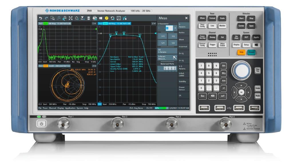
 Signal Analyzers
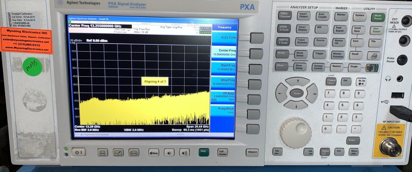
 Logic Analyzers
 Optical Spectrum Analyzers
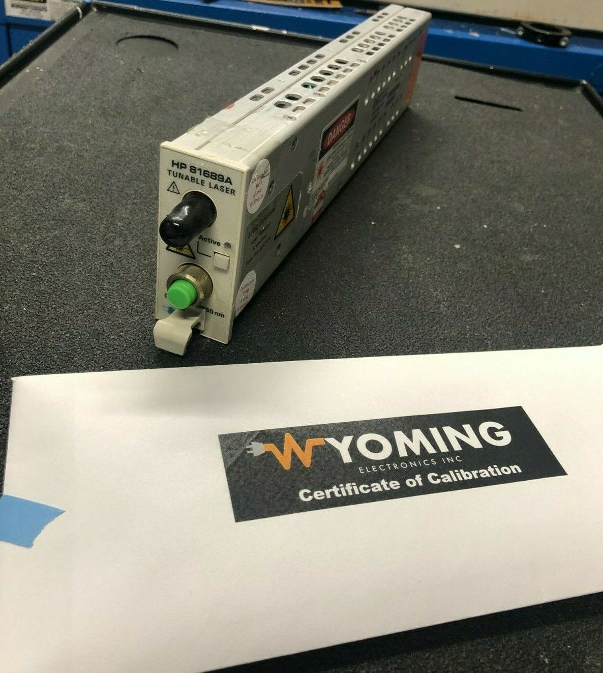
 Other Analyzers
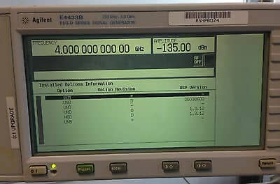
 Signal Generator
 Function Generator
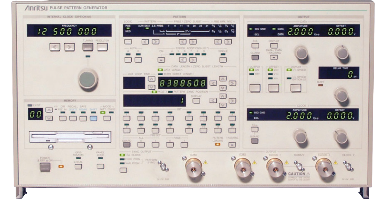 Pulse / Pattern Generator
 Waveform Generator
 Other Generators
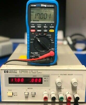
 Digital Multimeter
 Power Meter
 Frequency Counters
 Optical Power Meter
 Wavelength Meter
 Receiver
 Current/Power Source Meter
 Picoammeter
 Other Meters
 Optical Fiber
 Fiber Cleaver
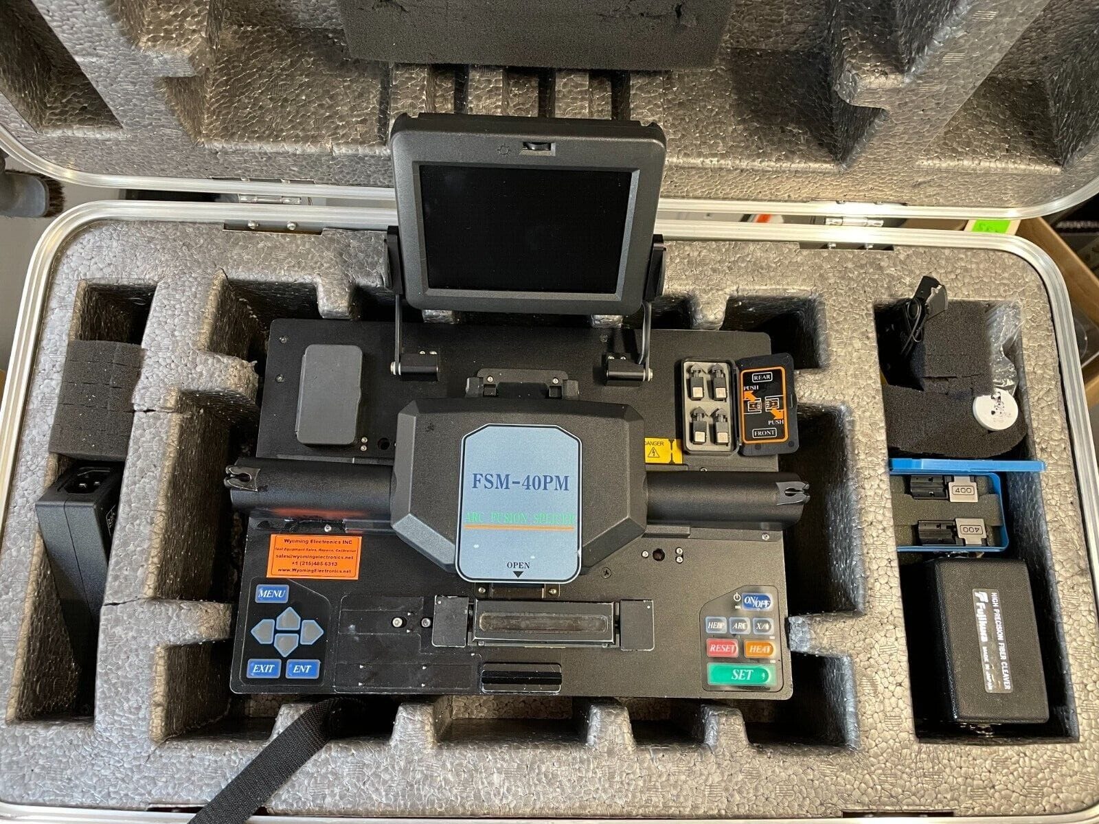
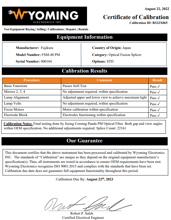
 Fusion Splicer
 Fiber Recoater
 Optical Attenuator
 Optical Head
 OTDR (Optical Time-Domain Reflectometer)
 Other Optical Instruments
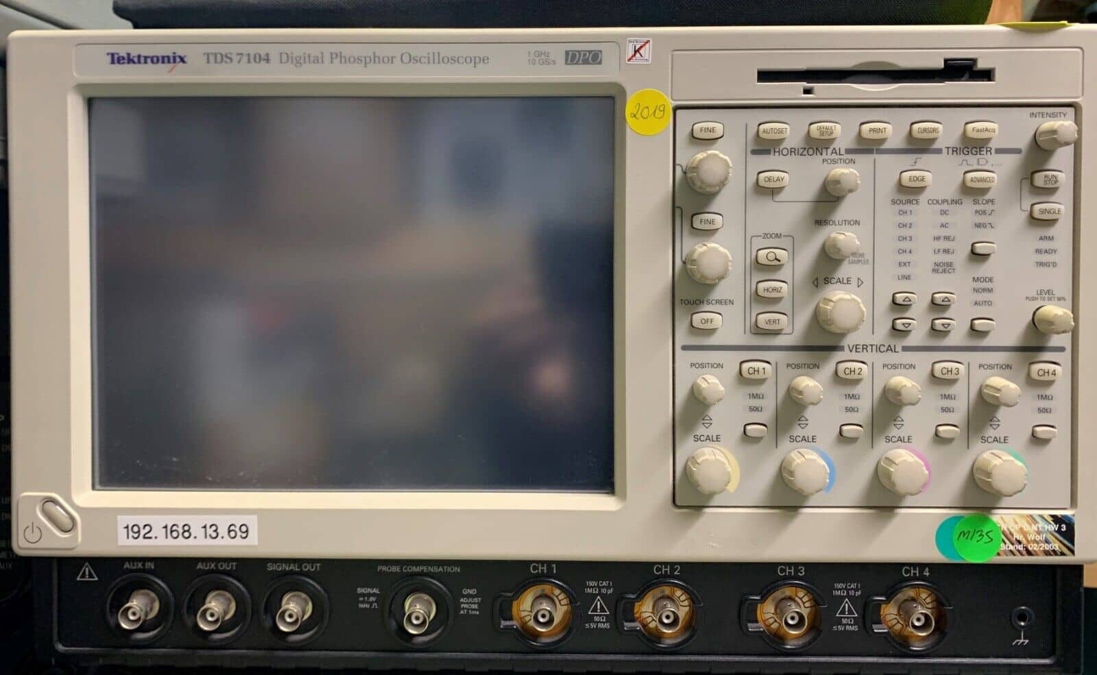
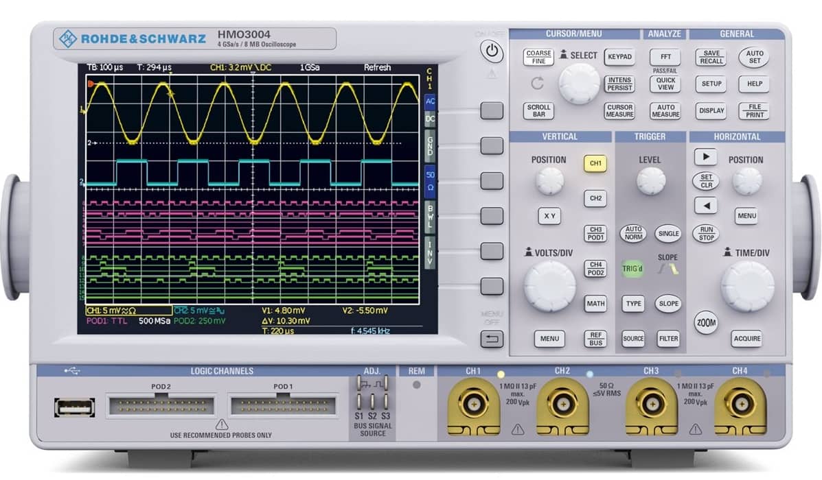
 Oscilloscopes
 Curve Tracer
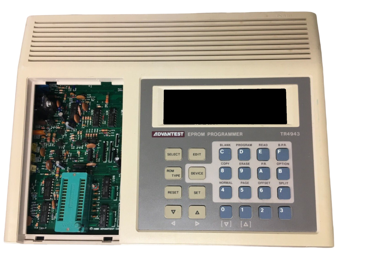 EPROM Programer
 Recorder
 Data Acquisition System
 Data Logger
 Calibration Kit
 Verification Kit
 Test Set
 Test Chamber / Ovens
 Calibrator
 Controller
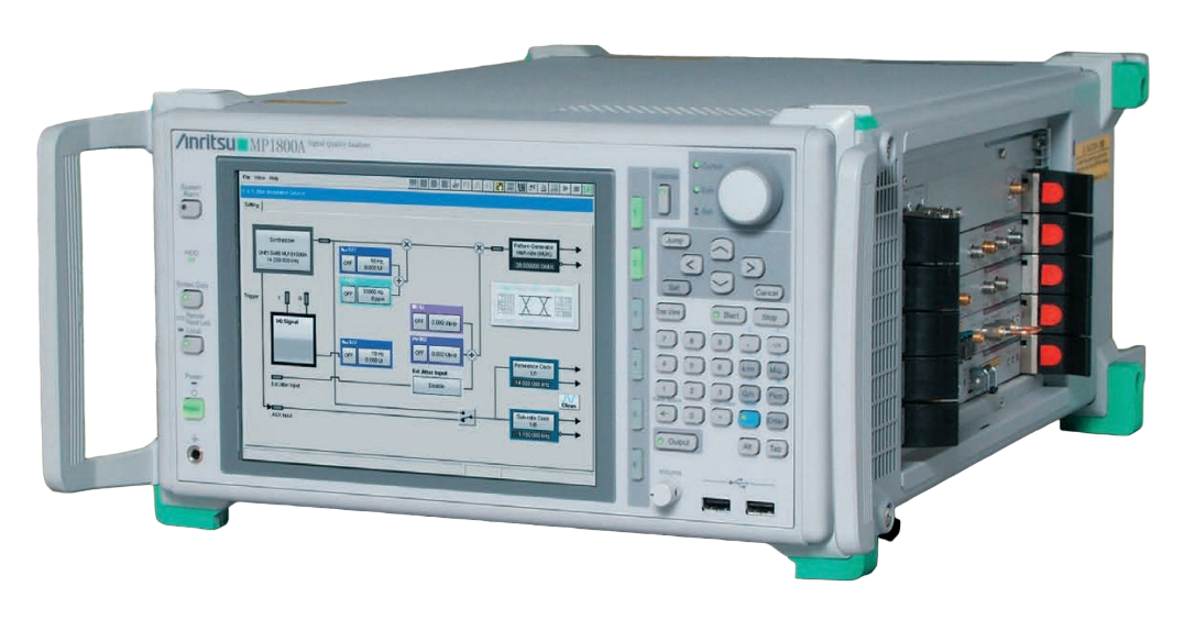 Mainframe
 Module
 Interfaces(GPIB, Power)
 Switch
 Matrix Cards
 Converter
 Multiplexer
 Plug-in
 Simulator
 LCR Meters
 Filters
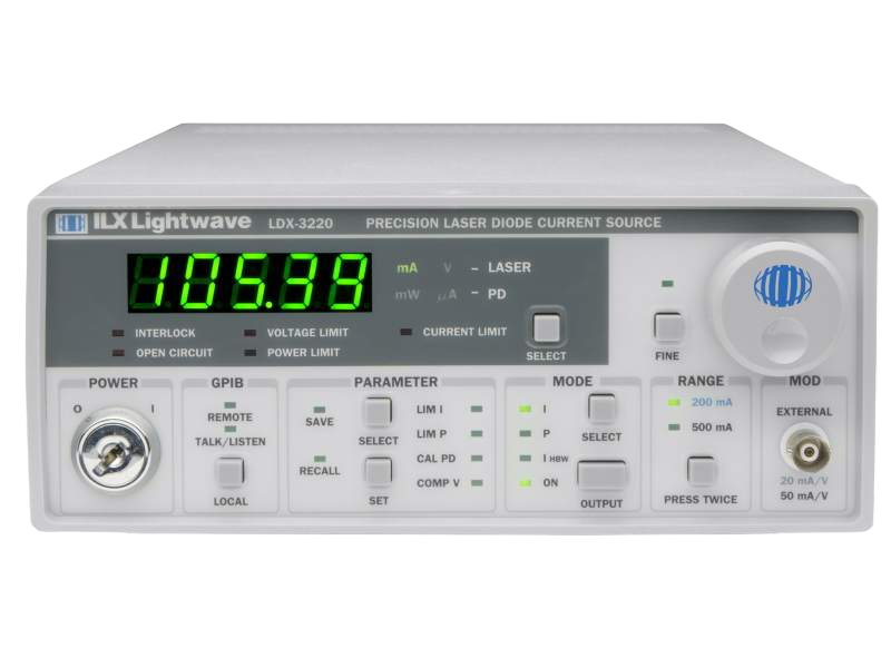 Laser Drivers
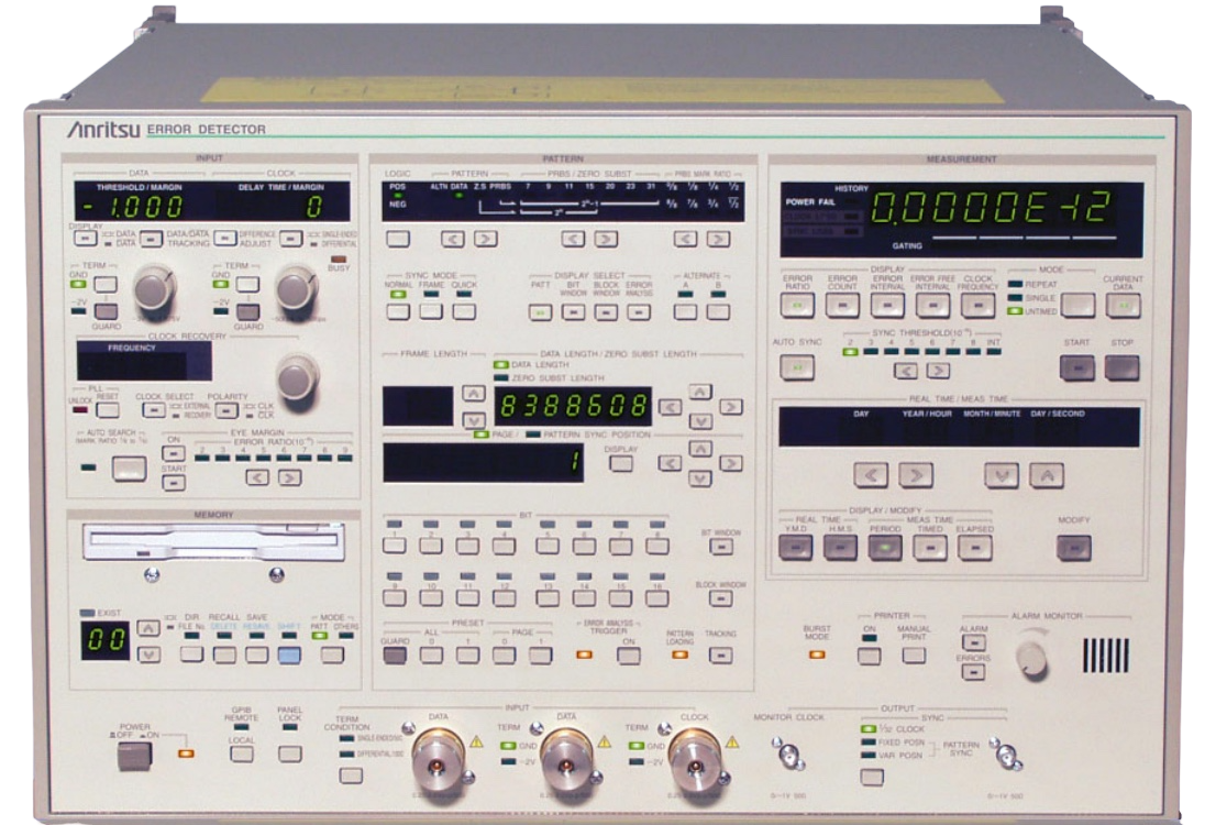 Error Detectors
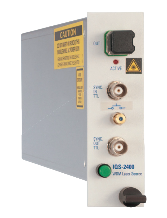 Laser Source
 Probe
Probe Power Sensor
 Amplifier
 Attenuator
 Optical Sensor
 Light/LED Source
 Broadband / Noise Source
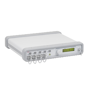 Optical / Fiber Source
 Power Supply
 Voltage Source
 Polisher
 Microscope
 Adapter
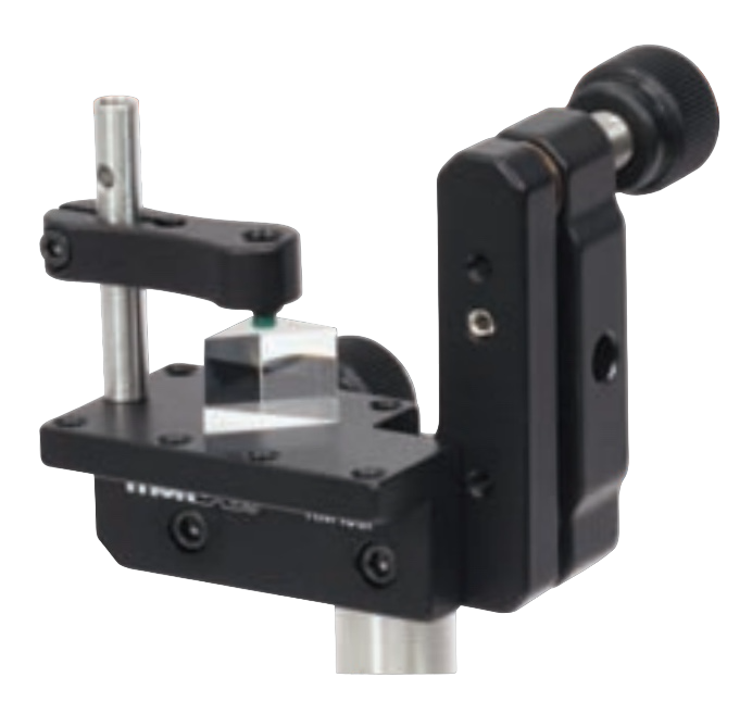 Platforms/Mounts
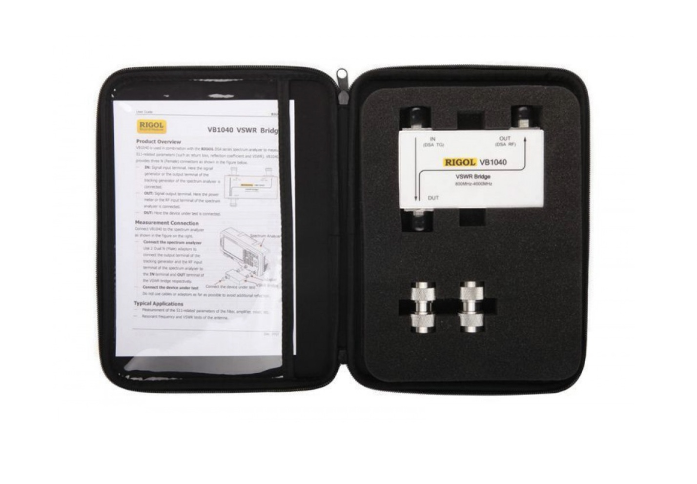 Bridges
 Connectors & Accessories
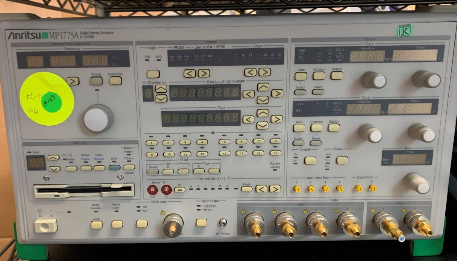
In the world of digital communication, precise signal generation and testing are critical for ensuring optimal performance and reliability. One tool that has revolutionized this process is the pulse pattern generator. With its ability to generate complex, high-speed digital signals, pulse pattern generators have become indispensable in various industries. In this blog post, we will delve into the fascinating world of pulse pattern generators, exploring their functionalities, benefits, and applications. Let’s unlock the potential of this remarkable tool together.
Understanding Pulse Pattern Generators:
Pulse pattern generators, also known as bit pattern generators, are sophisticated electronic instruments used to generate digital signals with specific patterns and characteristics. They provide a versatile platform for creating complex data patterns, clock signals, and test vectors for digital communication systems and devices. Pulse pattern generators can produce a wide range of signal formats, including high-speed serial data, pseudo-random bit sequences (PRBS), and user-defined patterns.
Benefits of Pulse Pattern Generators:
2.1 Signal Quality and Precision: Pulse pattern generators offer precise control over the characteristics of the generated signals, including amplitude, rise/fall times, duty cycle, and transition times. This level of control ensures accurate and reliable testing of digital systems and enables engineers to evaluate signal integrity, analyze performance, and detect potential issues.
2.2 Flexibility and Customization: Pulse pattern generators provide the flexibility to generate a variety of signal patterns and formats to meet specific testing requirements. They allow users to create complex data patterns and simulate real-world scenarios to evaluate the performance and compatibility of digital devices, components, and communication protocols.
2.3 High-Speed Testing Capabilities: With the ever-increasing speeds of digital communication systems, pulse pattern generators excel at generating high-speed signals. They can generate signals with data rates ranging from a few megabits per second (Mbps) to several gigabits per second (Gbps) or even higher. This capability makes them indispensable for testing high-speed serial interfaces, such as Ethernet, USB, HDMI, and PCIe.
2.4 Error Detection and Analysis: Pulse pattern generators often incorporate advanced error detection and analysis features, such as bit error rate (BER) testing and eye diagram analysis. These capabilities enable engineers to assess the quality of the received signal, identify potential errors or distortions, and optimize system performance.
Applications of Pulse Pattern Generators:
3.1 Digital System Testing: Pulse pattern generators are extensively used for testing and validating digital systems, including integrated circuits (ICs), field-programmable gate arrays (FPGAs), and digital signal processors (DSPs). They aid in functional testing, performance characterization, and compliance testing for industry standards.
3.2 Serial Interface Testing: Pulse pattern generators play a crucial role in testing high-speed serial interfaces, ensuring compliance with industry standards and validating the performance of communication links. They help verify signal integrity, evaluate jitter and noise characteristics, and assess error rates for interfaces like PCIe, USB, SATA, and HDMI.
3.3 Protocol Testing: Pulse pattern generators facilitate protocol testing by generating specific bit sequences or data patterns that conform to various communication protocols. This allows engineers to test the compatibility, interoperability, and performance of devices adhering to standards such as Ethernet, Fibre Channel, and InfiniBand.
3.4 Digital Communication Research and Development: In research and development environments, pulse pattern generators assist in the design and evaluation of new communication technologies. They enable researchers to simulate and analyze complex data patterns, investigate signal impairments, and validate innovative algorithms for error correction, equalization, and modulation.
Choosing the Right Pulse Pattern Generator:
When selecting a pulse pattern generator, consider the following factors:
4.1 Signal Generation Capabilities: Evaluate the required signal formats, data rates, and pattern lengths that your application demands. Ensure that the pulse pattern generator can support the necessary parameters for accurate testing.
4.2 Flexibility and Customization: Look for a pulse pattern generator that offers flexibility in creating custom patterns and sequences to match your specific testing requirements. The ability to import user-defined patterns can be a valuable feature.
4.3 Signal Integrity and Output Quality: Consider the output characteristics of the pulse pattern generator, including amplitude accuracy, rise/fall times, and jitter performance. Ensure that the generator can deliver signals with the required fidelity for accurate testing.
4.4 Error Detection and Analysis Features: If your application involves error detection or eye diagram analysis, choose a pulse pattern generator with built-in capabilities for efficient signal analysis and comprehensive error detection.
4.5 Integration and Connectivity: Consider the connectivity options and interfaces supported by the pulse pattern generator. Look for compatibility with other test equipment, such as oscilloscopes, logic analyzers, and protocol analyzers, to create a seamless testing setup.
Check out the pulse pattern generators offered by Wyoming Electronics Inc.
How pulse pattern generator works
Pulse pattern generators are essential tools in the field of digital communication testing, enabling engineers to generate precise digital signals for various applications. In this blog post, we will take a closer look at how pulse pattern generators work and the underlying principles that govern their operation. Understanding the inner workings of these devices will shed light on their capabilities and empower you to leverage them effectively for your testing needs.
Signal Generation:
At its core, a pulse pattern generator is designed to generate digital signals with specific patterns and characteristics. To achieve this, it employs a combination of digital logic circuitry, waveform memory, and clock generation mechanisms.
Digital Logic Circuitry:
The pulse pattern generator contains digital logic circuitry that processes and manipulates digital data to generate the desired signal pattern. This circuitry includes components such as counters, shift registers, multiplexers, and logic gates. These elements work together to generate the sequence of digital values that form the pattern.
Waveform Memory:
Pulse pattern generators often incorporate waveform memory, which stores predefined digital patterns or sequences. This memory can hold a large number of digital values, allowing for the generation of complex patterns and long data sequences. The stored patterns can include repeating bit patterns, pseudo-random bit sequences (PRBS), or user-defined patterns.
Clock Generation:
A crucial aspect of a pulse pattern generator is the generation of a clock signal, which determines the timing and rate at which the digital pattern is outputted. The generator typically includes a clock source, such as a crystal oscillator, that provides a stable and precise timing reference. The clock signal synchronizes the digital logic circuitry, ensuring accurate generation of the desired signal pattern.
Pattern Control and Configuration:
Pulse pattern generators offer various control and configuration options to tailor the generated signal according to specific testing requirements. These options may include setting the data rate, adjusting the pattern length, modifying the duty cycle, or selecting predefined patterns. Some advanced pulse pattern generators even allow for user-defined patterns, enabling greater flexibility and customization.
Signal Conditioning and Output:
To ensure the generated signal meets the desired characteristics, pulse pattern generators incorporate signal conditioning components. These components shape the digital signal, controlling parameters such as rise/fall times, amplitude levels, and edge transitions. The conditioned signal is then amplified and presented at the output port of the pulse pattern generator.
Error Detection and Analysis:
Many pulse pattern generators offer advanced features for error detection and analysis. They can incorporate error detectors to compare the generated signal with a reference signal, enabling the measurement of parameters such as bit error rate (BER) or eye diagram analysis. These features help evaluate the quality and integrity of the generated signal and identify any potential issues.
Integration and Connectivity:
Pulse pattern generators often provide integration and connectivity options, allowing for seamless integration into testing setups. They may offer various interfaces such as Ethernet, USB, GPIB (General Purpose Interface Bus), or PCIe (Peripheral Component Interconnect Express) for easy communication with other test equipment, such as oscilloscopes or logic analyzers.